Kuvagalleria
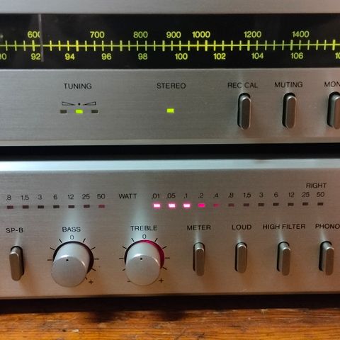
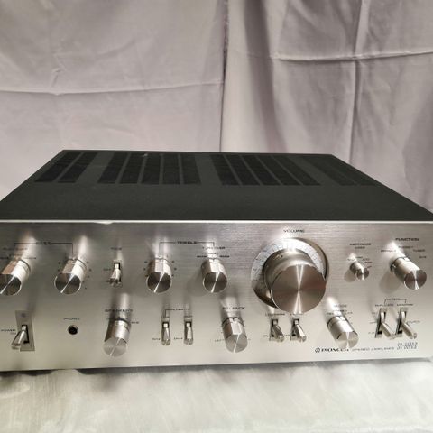
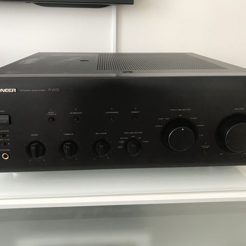
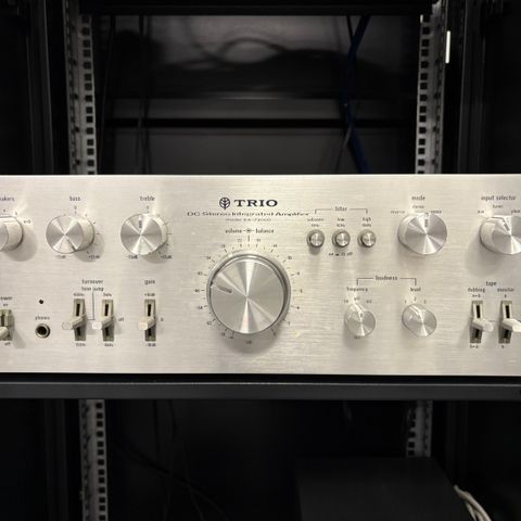
Pioneer SA-9900 Stereo vahvistin
Tuotteen kuvaus
Kunto: Hyvä
Merkki: Pioneer
Ihan siisti ja täysin ehjä vahvistin. Huollettu. 100V japanilainen versio ja muuntaja mukaan.
Commentary
A pre-main amplifier that pursues high output and low distortion and employs a unique side terminal system.
The side terminal method is adopted. The input terminals are integrated with the equalizer board, and the shield line connecting the phono terminal and the equalizer terminal is eliminated to prevent degradation of the high-frequency characteristics due to stray capacitance of the shield line.
All stages of the power amplifier are directly connected and pure complimentary service OCL circuit with 3-stage Darlington connection, and the output stage is parallel push-pull type.
The 2-stage differential amplifier and bias compensation circuit provide sufficient stability by controlling the DC component to the speaker terminal even when there is a change in external temperature.
The two constant-current circuits expand the operating range of the transistor and increase the bare characteristics of the circuit. Moreover, not only NFB from the output stage but also appropriate NFB is applied to the differential part to improve the bare characteristics.
In addition, by applying NFB from the output stage, deterioration and instability of transient characteristics are eliminated. Furthermore, by providing a large time constant to this circuit, phase shift in the ultra-low frequency range is eliminated.
The constant current circuit suppresses changes in the idle current due to fluctuations in the power supply voltage, and the newly developed bias supply method enables constant compensation for temperature differences between transistors caused by self-overheating of transistors, eliminating transient crossover distortion with a stable idle current from high power to minute output.
In addition, by floating the emitter resistor of the driver stage from the midpoint and operating it as class A until very large amplitude, crossover distortion in this stage is eliminated.
We use carefully selected power transistors with excellent characteristics and strong breaking strength. We also use a large radiator to prevent trouble. In addition, we use an electronic protective circuit using relays and a current limiting circuit.
In addition, a newly developed temperature detection circuit is used to control the supply voltage of the output stage when the temperature of the radiator reaches 85 ° C or higher to keep the temperature of the radiator within a certain range.
The first stage of the EQ circuit is a low-noise FET differential amplifier designed to stabilize the mid-point and reduce the audible noise level. The second stage voltage amplifier uses a constant current load to obtain a linear Takamasu depth and improve the distortion characteristics. The SN ratio is also improved by using a noise-selective transistor.
The circuit is supplied with a high voltage of ± 48 v to ensure a sufficient dynamic margin, and the NFB element for the RIAA curve uses a Nichrome metal-coated resistor with very low error and a Styrofoam capacitor to obtain excellent characteristics.
The level of the Phono2 input can be adjusted up to -12dB. Up to -6dB is done with an NFB circuit, and from -6dB to -12dB is done with the sy volume. When the input is limited to -6dB or more, the maximum allowable input becomes approximately twice as large as 1 V.
Also equipped with 4-point switching impedance switching.
In the first stage of the control circuit, an FET differential amplifier that can apply 100% of DC NFB is installed, and ± 48 v is supplied by a 2-power supply system. The SN ratio is raised by the adoption of FET, and click noise when switching is prevented by the 2-power supply system.
As well as the equalizer circuit, the voltage amplifier circuit uses a constant current load to improve the bare characteristics of the circuit. Moreover, since no bootstrap circuit is used, the phase characteristics and transient characteristics in the low frequency range are improved.
The tone circuit uses a twin-tone control method, which allows general tone control for the main only operation, ultra-high and ultra-low frequency control for the sub only operation, and a wide range of control by combining the main and sub.
For these two controls, the main is NFB type and the sub is CR type, and a tone control on/off switch is installed.
The volume is a true attenuator-type volume with a 22-contact high-precision printed resistor with 2 dB-step decibels for direct reading of attenuation, illuminated by an edge light.
Also equipped with a lever type attenuator that can be switched to 3 stages.
The power supply section is equipped with two 22,000 μ F large electrolytic capacitors.
Equipped with 2-step switching type low-cut / high-cut filter.
It is equipped with a duplicate switch. By turning on the switch, you can copy tapes from 1 to 2 and from 2 to 1.
Data on actual measurement of each product is attached to each product.
Model Rating
Type Stereo pre-main amplifier
Power Amplifier Unit
Circuit system Differential 2-stage 3-stage Darlington Parallel Pushpull Pure complimentary service OCL
Effective power
(Both channel drive, 20 Hz to 20 kHz) 110W + 110W (4 Ω)
110W + 110W (8 Ω)
Harmonic distortion factor (20 Hz to 20 kHz) 0.1% or Less (Effective Output)
0.04% or Less (8 Ω at 55W output)
0.04% or Less (8 Ω at 1W output)
Cross modulation distortion factor 0.1% or Less (Effective Output)
0.04% or Less (8 Ω at 55W output)
0.04% or Less (8 Ω at 1W output)
Output Bandwidth (IHF, both channel drives) 5 Hz ~ 40 kHz (Distortion Factor 0.1%)
Frequency characteristic 10 Hz to 80 kHz + 0 -1dB
Input Sensitivity / Impedance Power amp in : 1V/50k Ω
Output terminal Speaker A / B : 4 Ω ~ 16 Ω
Speaker A + B : 8 Ω ~ 16 Ω
Headphone : 4 Ω ~ 16 Ω
Damping factor 30 or More (20 Hz to 20 kHz)
S/N 110 dB or more (IHF, A-network, short circuit)
Preamplifier Section
Circuit system Equalizer amplifier : Positive and negative 2 power supply, FET differential 1-stage 3-stage direct connection A class SEPP
Control amplifier : Positive / negative 2 power supply, FET differential 1 stage / 3 stage connected
Input Sensitivity / Impedance Phono1 : 2.5mV/50k Ω
Phono2 : 2.5 to 10mV/35k Ω, 50k Ω, 70k Ω, 100k Ω
Tuner, Aux1, 2, Tape PB1, 2 : 150mV/50k Ω
Phono maximum allowable input
(Harmonic distortion rate 0.1%, 1 kHz) Phono1:500mV
Phono2 : 500 mV to 1.0 V
Output Level / Impedance Tape Rec1, 2 : 150 mv
Pre-out : 2V/1k Ω
Harmonic distortion factor (20 Hz to 20 kHz) Not more than 0.05%
Frequency characteristic Phono (RIAA deviation) : 30 Hz to 15 kHz ± 0.2 dB
Tuner, Aux, Tape PB : 7 7 hz to 40 khz + 0 to 1 db
Tone control 1.5 dB step
Bass Sub : + / - 4.5 dB (50 Hz)
Main : ± 7.5 dB (100 Hz)
Treble Sub : ± 4.5 dB (20 kHz)
Main : ± 7.5 dB at 10 kHz
Filter Low : 15 Hz, 30 Hz, 12dB/oct.
High : 8 kHz, 12 kHz, 12dB/oct.
Muting 0, -15dB, -30dB
S/N (IHF, A-network
Short circuit) Phono : 70 dB or more
Tuner, Aux, Tape PB : 95 dB or higher
Semiconductor used Transistor : 74
FET : 10
Diode, etc. : 33 pcs
AC outlet Power switch interlock : 2 systems
Power switch not linked : 1 system
Power supply voltage 100 VAC, 50Hz/60Hz
Power consumption 270W (rated)
730W maximum
External dimensions Width 420x Height 165x Depth 403 mm
Weight 20.0kg
Käyttäjäprofiili

Kirjaudu sisään, jos haluat nähdä profiilin ja lähettää viestejä.
Kirjaudu sisäänIlmoituksen metatiedot
Viimeksi muokattu: 24.12.2024 klo 16.27 ・ Ilmoituksen tunnus: 18197563
Samankaltaisia ilmoituksia
50 €
